The High Voltage Supply for the Large Prototpe
A high voltage (HV) system is one of the main sub-systems of a detector like the Large Prototype (LP). It not only provides the voltages necessary for the operation of the detector, but also controls them to run the detector safely.
In context of the HV system the LP has four main components: the cathode plate, the field cage, the anode termination plate, and the detector modules. Their mechanical arrangement (described elsewhere) separates them, electrically, from one another. Thus, each of these components has to be powered independently, and their voltages maintained correctly to prevent dangerous sparks from developing between them at all times during the detector operation. In the proposed HV system for the LP this will be achieved by driving their HV supplies by means of computers.
Up to seven detector modules can be installed inside the LPTPC on the anode side. The type and the number of detector module will vary from setup to setup. Each detector module can have either one HV terminal (for example, in MicroMEGAS modules), or up to seven HV terminals (for example, in triple-GEM modules with a gate). Thus, the number of HV channels will vary, and so will their settings and parameters. The HV system and the slow-control software will be designed to meet these needs.
The slow-control application for the HV system will be implemented using the DOOCS framework. DOOCS is a distributed control system developed by the DOOCS team at DESY. The slow-control application will control and monitor the HV system. A graphic user interface will allow user to issue commands, change the configuration and monitor the system status.
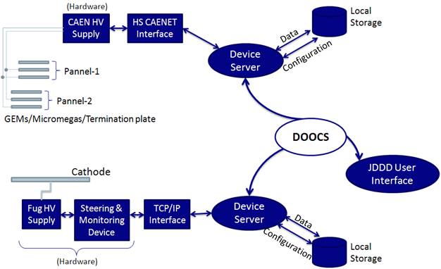
Schematic layout of the high voltage system and its connection to the slow control system.