Gas Electron Multipliers
The GEM (Gas Electron Multiplier) technology, which has been introduced by F. Sauli in 1996 and is in use in high energy and medical physics, provides the possibility to avoid the problems mentioned on the pages about wire amplification.
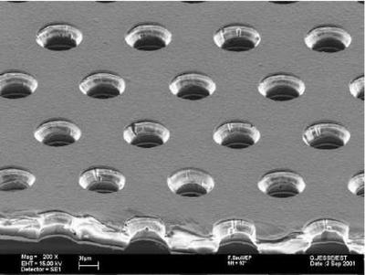
The standard CERN GEMs consist of an insulator made of a thin Kapton foil (about 50 μm) which is coated on both sides with copper layers (about 5 μm). This structure is perforated with holes that typically have a diameter of 70 μm and a pitch of 140 μm. The holes are arranged in a hexagonal pattern. Due to an etching production process they have a double conical shape with an inner diameter of about 55 μm. Besides the CERN GEMs, also other companies are now producing GEM foils, that vary in hole size, shape as well as the insulator thickness and material. Figure 1 shows a picture of a GEM that has been taken with an electron microscope.
Figure 1: Image of the GEM structure taken with an electron microscope (image from CERN GDD group).
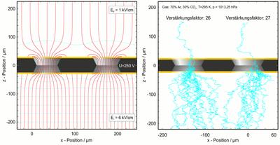
The working principle of the GEMs is shown in Figure 2. Between the two copper coatings a voltage of a few 100 V is applied. Since the field lines are focused in the holes, there the resulting electric field strength is in the order of some 10 kV/cm which is high enough for the gas amplification. It is possible to achieve an amplification up to ten thousand, but usually a setup consists of two or three successive GEMs which are operated at a lower voltage and therefore run more stable.
Figure 2: Sketch of the working principle of a GEM. Left side shows the field lines (red) in a GEM hole. The right side shows the multiplication of a single electron -turquoise lines show electron paths- in GEM holes (both images by O. Schäfer).
Most electric field lines end on the side towards the cathode while on the other side most lines go into the direction of the anode. The ions from the gas amplification are pulled to and collected on the GEM surface while most of the electrons are extracted out of the GEM holes. The electron extraction is intensified if additionally a magnetic field is applied perpendicular to the GEM plane. The electrons tend to follow the magnetic field lines. The intrinsic ion back-drift suppression is one of the main advantages of the GEMs and makes a gating grid unnecessary.
Another advantage of the GEM amplification is the fast signal: the electron signal is measured directly on the pad plane, which leads to a better time (respectively Z) resolution. Furthermore, the GEMs do require less mounting structures as proportional wires do.
The GEM signal on the pad plane is narrower than in the case of proportional wires. This is an advantage in the two-track separation, but poses new problems in the rφ resolution. The pads have to be smaller, so that a narrow signal still hits enough pads for a good reconstruction in the rφ plane. However, the number of pads is limited by the feasible number of readout channels and the signal height (smaller pads result in a smaller signal per pad), so a compromise has to be found.
Overall GEMs are a very promising technique for the gas amplification in a TPC and many of their advantages already have been proven in protoype tests.


